The altimeter has been in use for approximately four months and nobody has died. Project is deemed great success and I can finally update the blog.
Actually now the PCB is in version 3 and fourth version is planned. More about progress of the PCB later.
Previous versions
So currently the PCB is at version 3. Version 1 was very quick and rough layout (45mm x 80mm) just to get the project started. It also contained GPS module but the there were lots of mistakes while laying the board near the module and I could not get connection to any satellites. I will be building new PCB for the GPS module again this winter but I’m fairly sure that the GPS can not fit into the existing case as it requires quite large and intact ground plane.
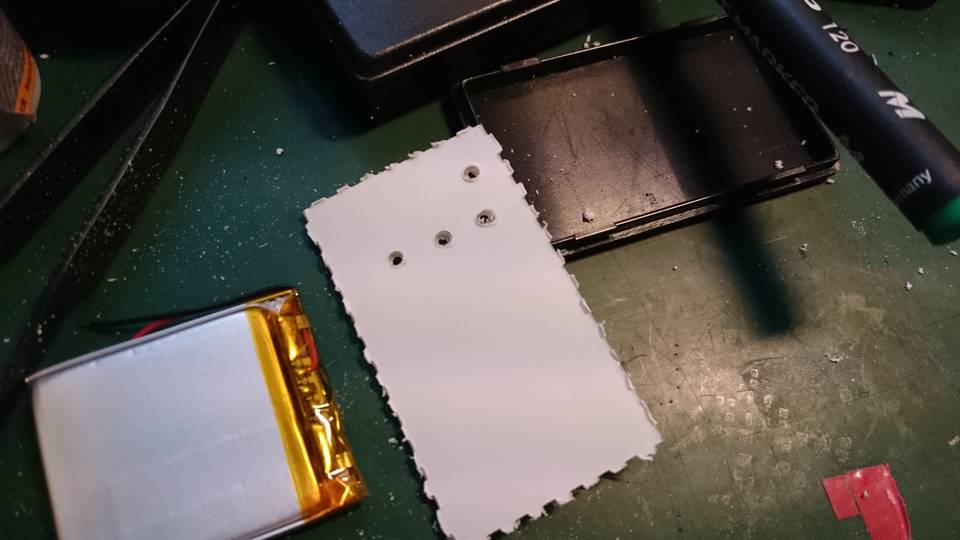
Second version was designed around small project case (30mm x 52mm) and contained mounting holes in each corner of the PCB. Micro-USB connector was planted on the long side of the PCB and for testing the buzzer there was two overlapping footprints for different buzzer components.
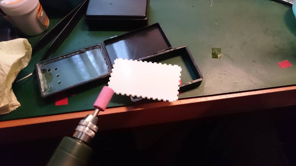
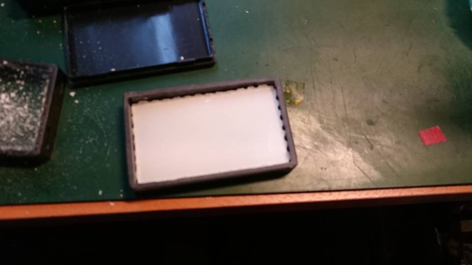
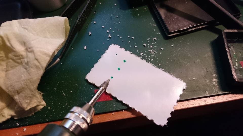
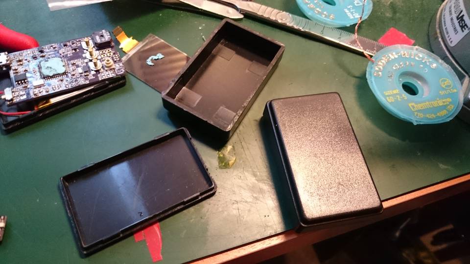
I ordered small laser cut acrylic case with 1mm wall thickness for the electronics but the case was too flimsy for actual use. The case laser cut profile was designed using MakerCase.
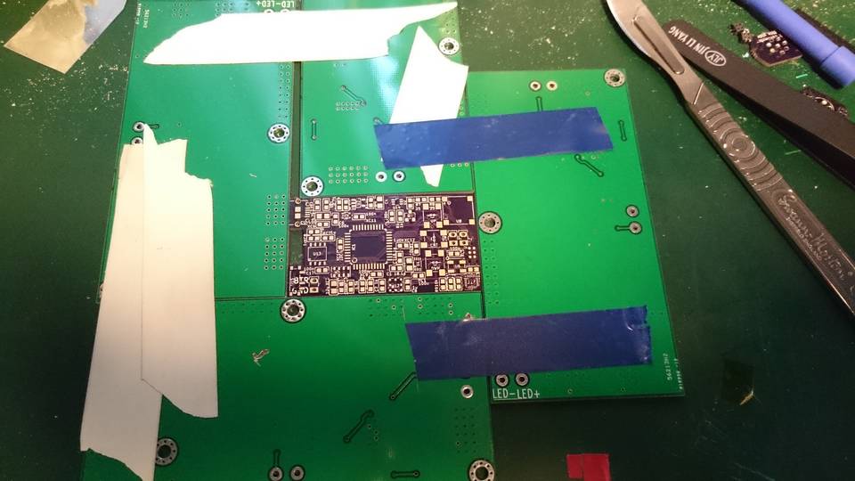
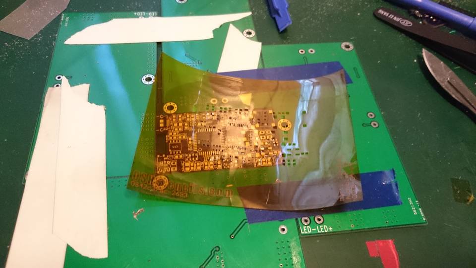
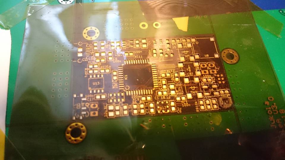
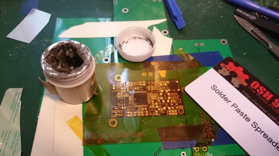
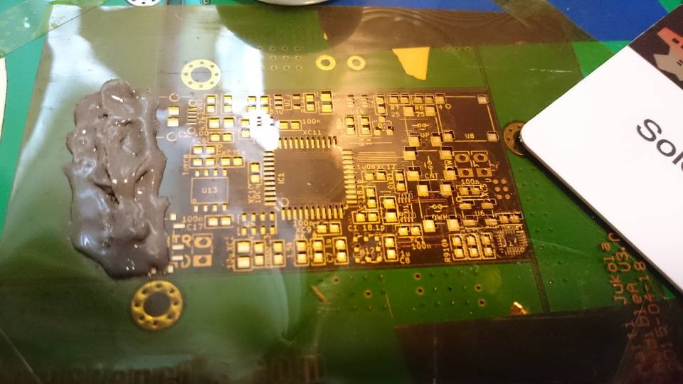
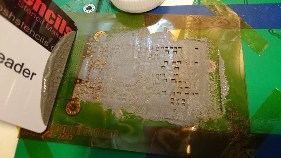
Stencil
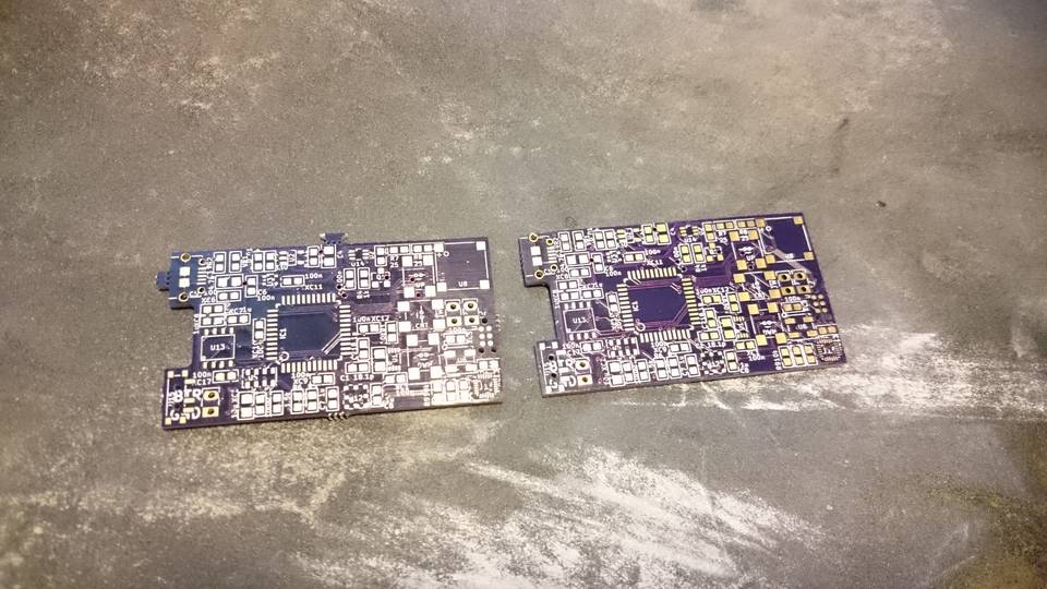
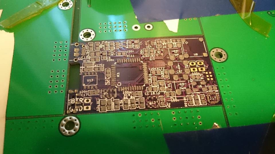
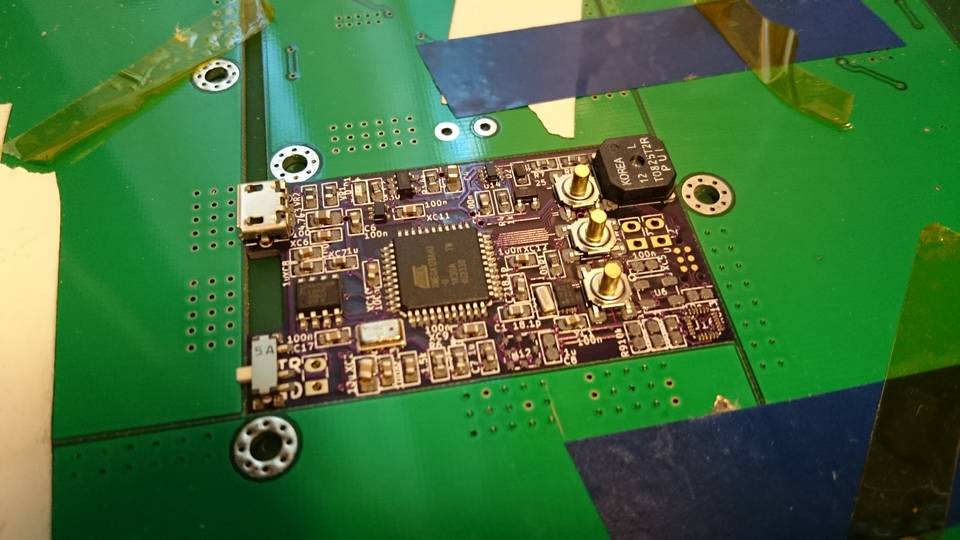
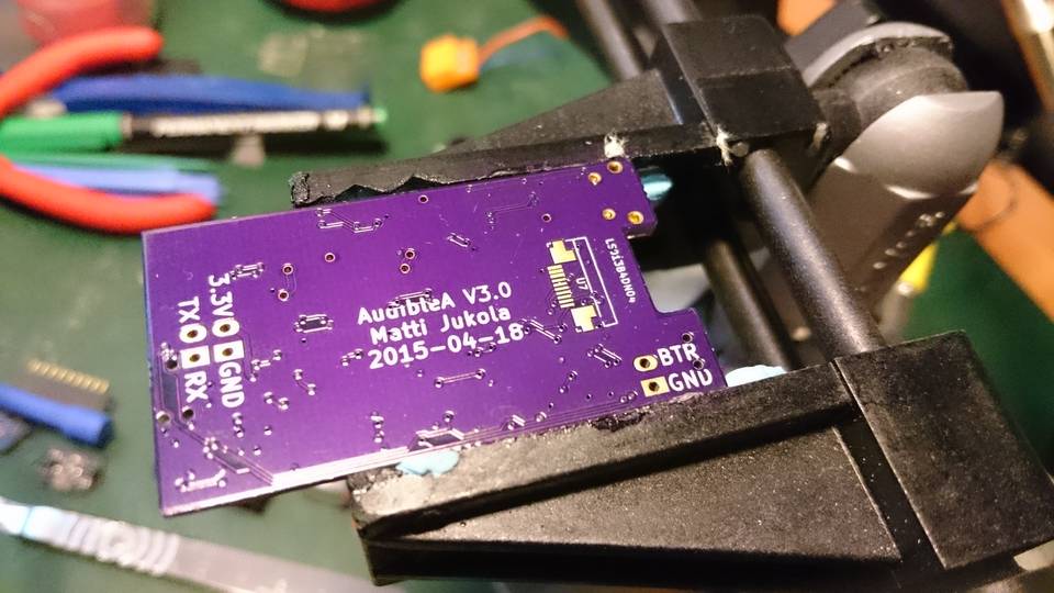
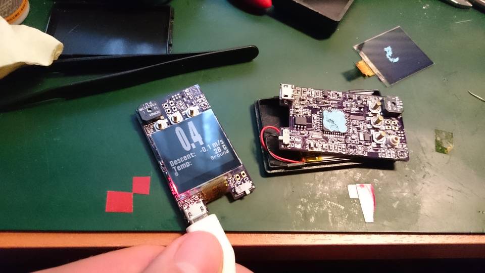
Version 3 PCBs arrived after three weeks of waiting.
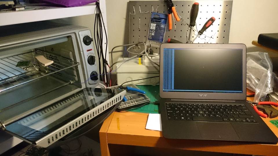
Before starting the altimeter project I had decided to start using reflow soldering. I build small oven controller which uses thermocouple, solid state relay, PWM and PID to control the oven temperature. Stencil for the applying the solder was ordered from OSH Stencils.
Laying components
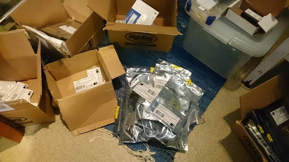
Most of the components were from Digikey but only place I could find the display was Mouser.
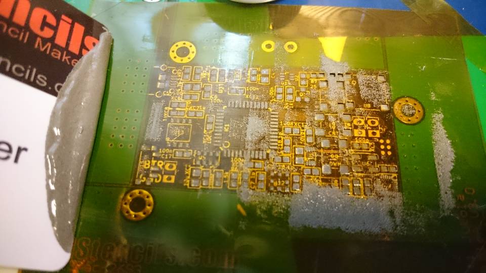
Reflow soldering
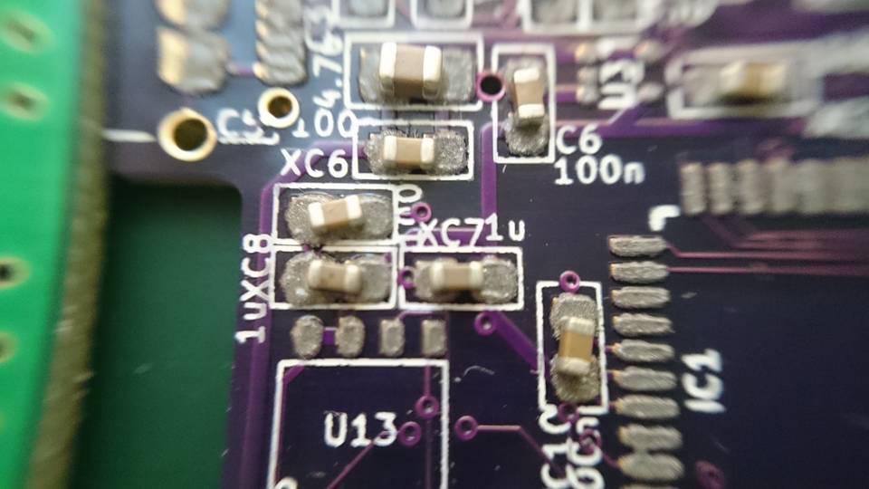
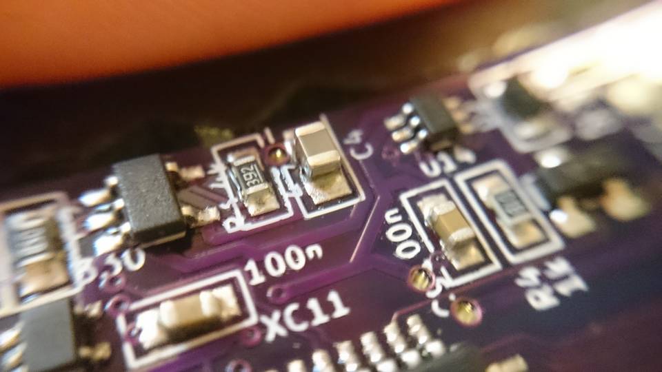
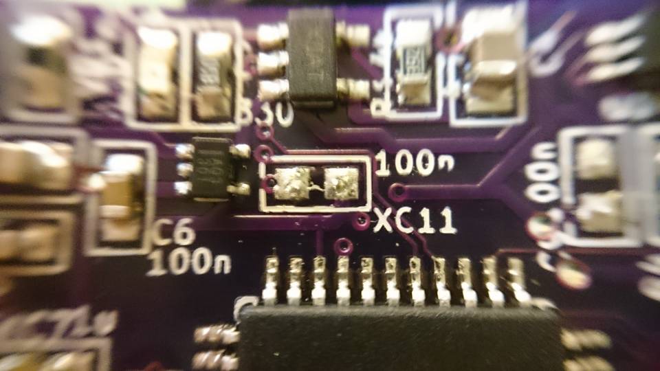
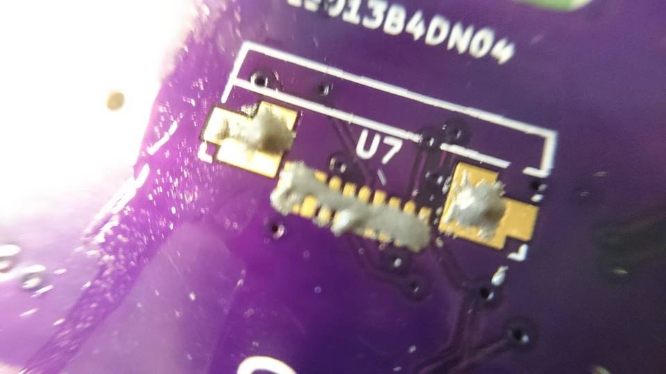
Bad component connections
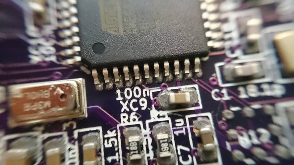
Applying the solder and the whole reflow soldering is not fully in my control as some of the components “tombstoned” (other end of the component lifted from the pad) or solder bridges were formed.
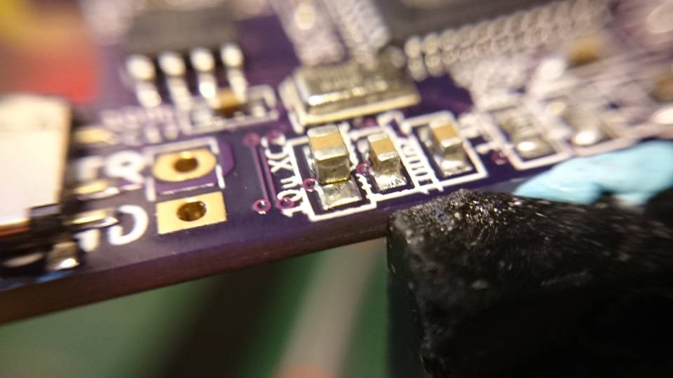
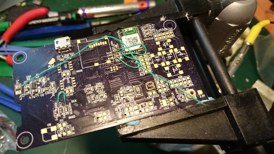
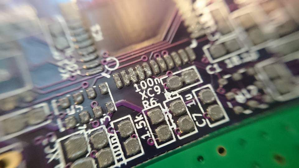
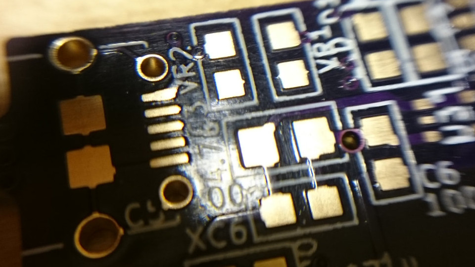
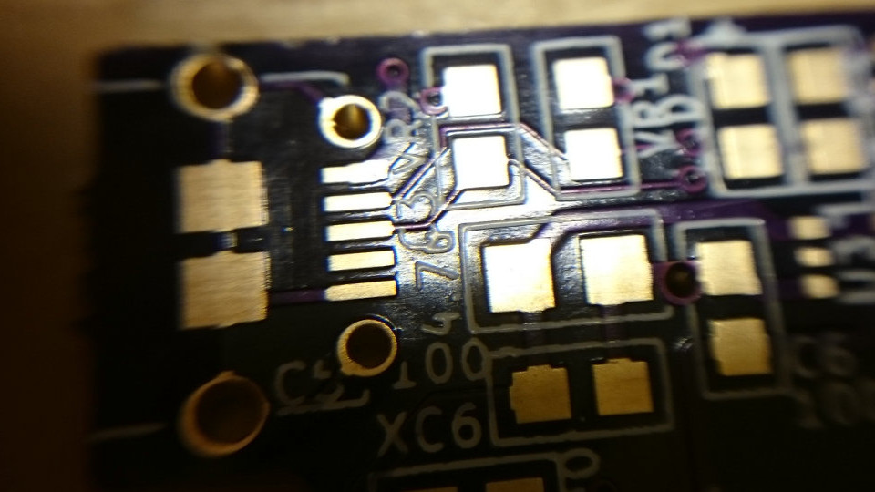
Version 3 – Bad traces
After assembling the PCB the USB failed to work. After pullimg my hair for few minutes I noticed that some of the USB traces were missing. This was fixed with small jumper wire.
I contacted OSH Park and let them know about the bad quality just so that process could be improved. They replied quickly and offered refund or free rush order + shipping. Good customer support!
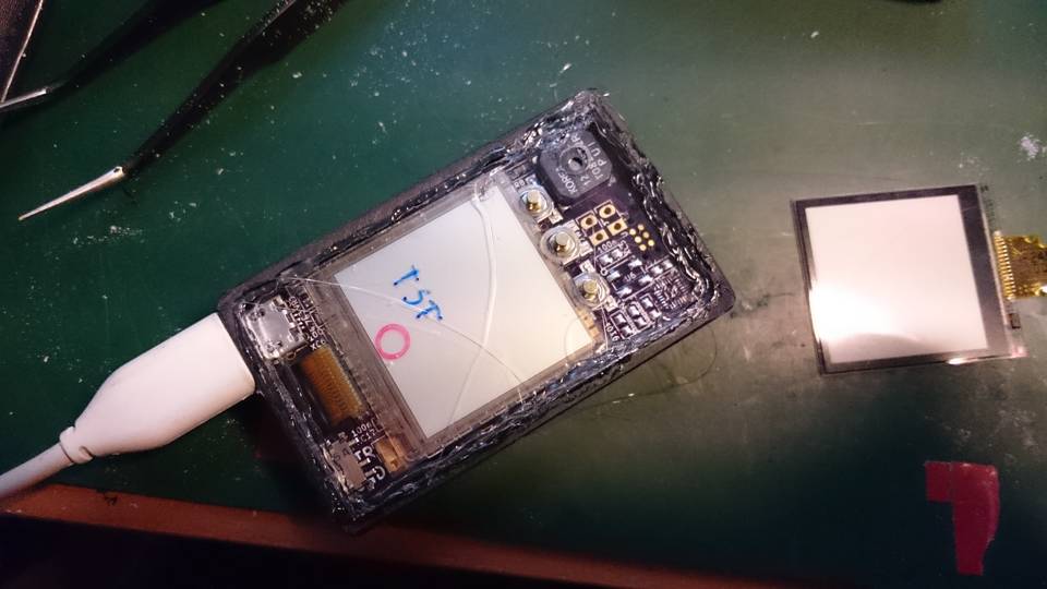
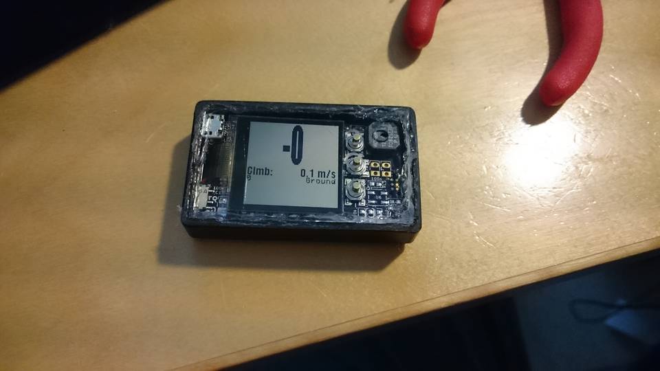
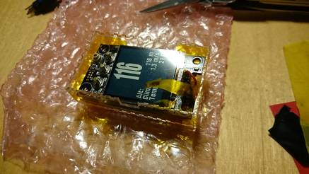
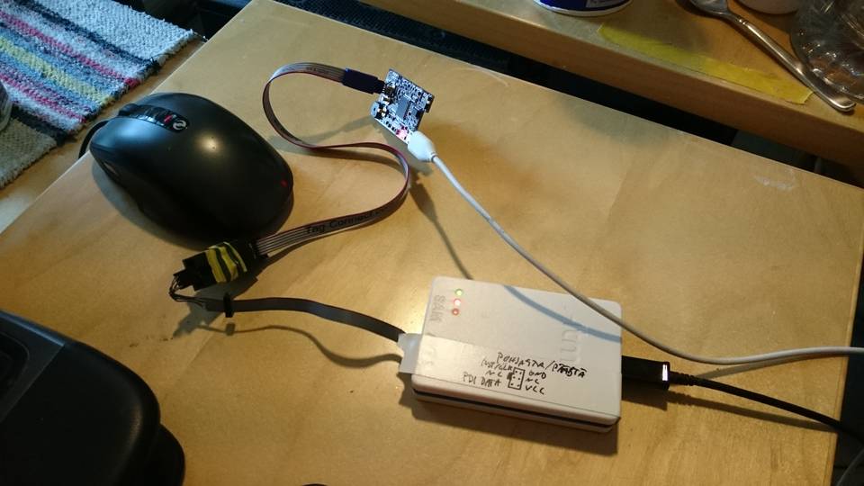
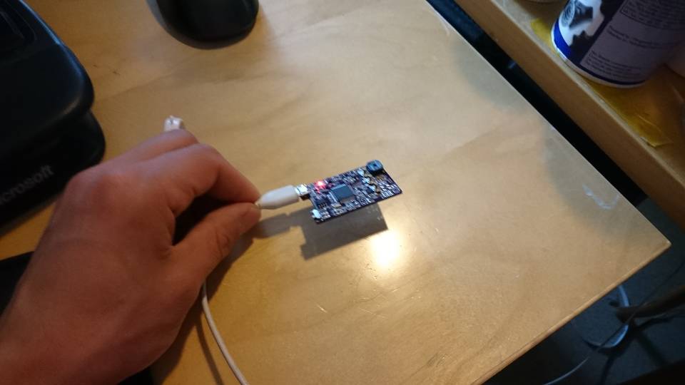
First boot
The MCU was programmed using Atmel ICE programmer. I’m using Tag-Connect cables as they have quite small footprint.
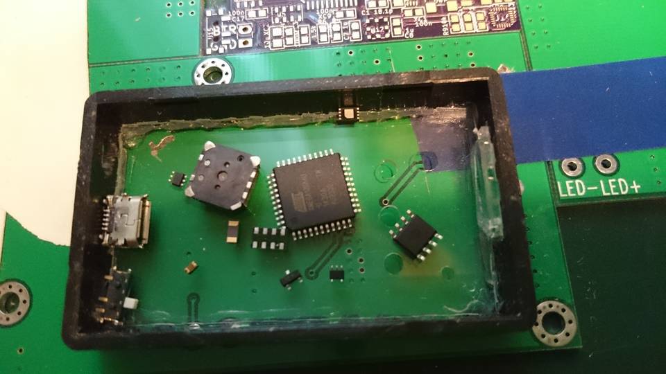
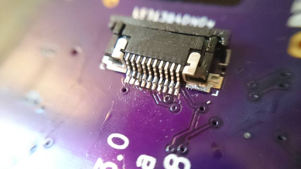
Display connector
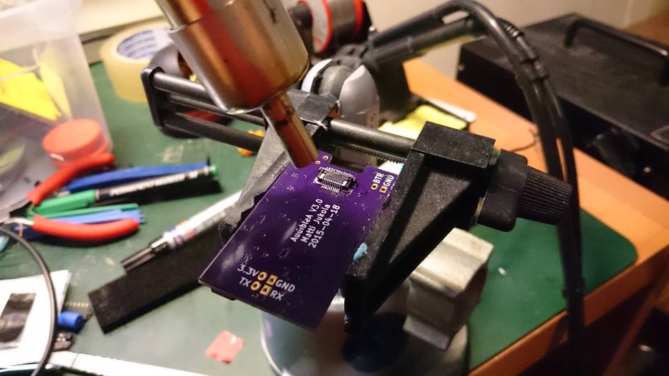
As the display connector is only component on the back side of the PCB I soldered it by hand.
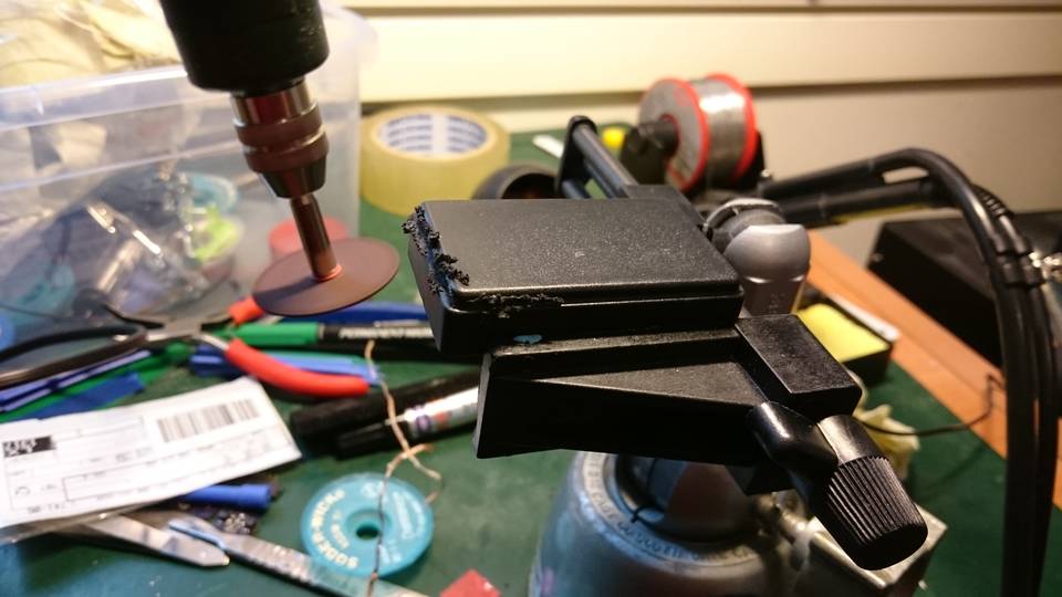
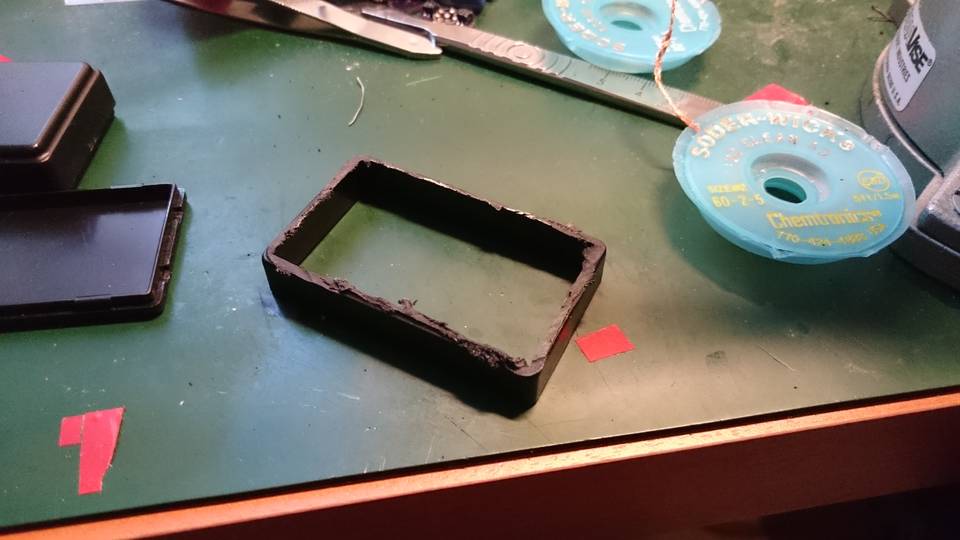
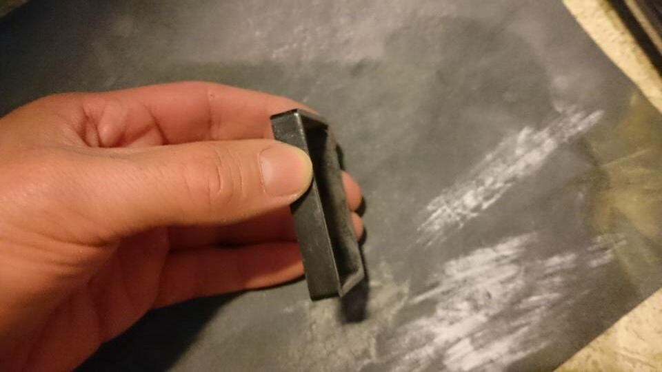
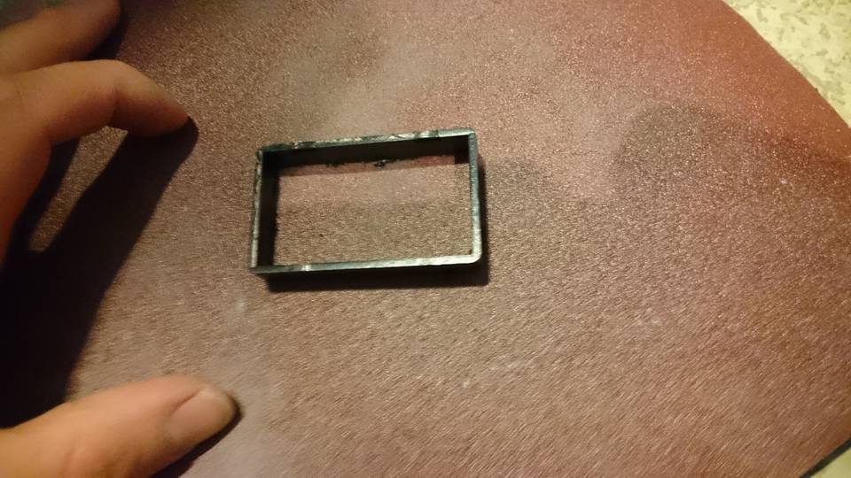
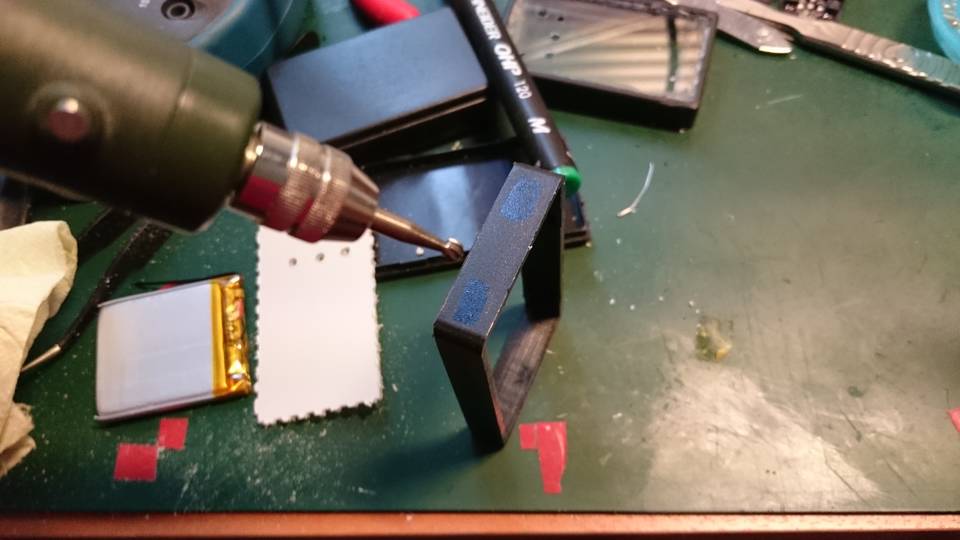
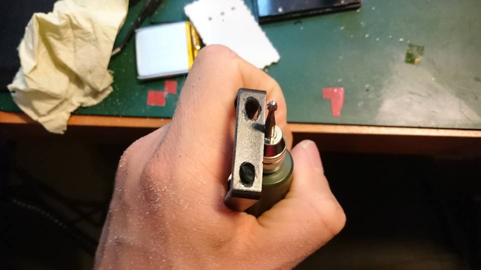
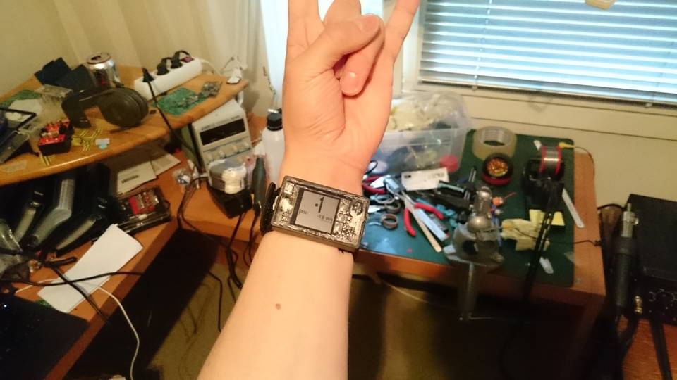
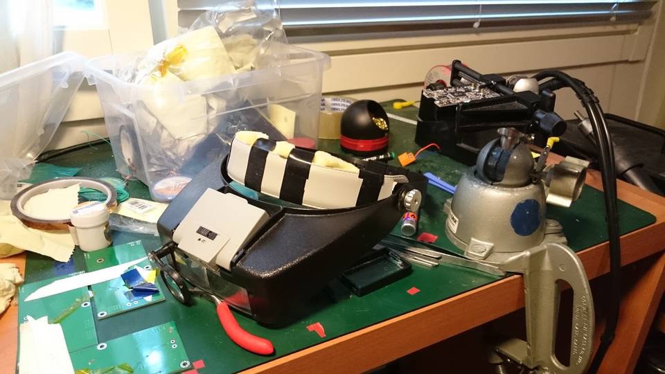
Case